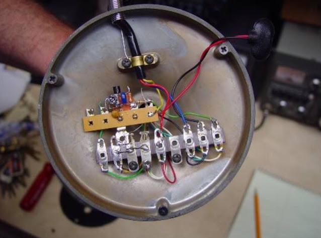
#13: D-104 Microphone amplifier / Equalizer for Ham Radio
This video describes the microphone preamp and equalizer that I designed in 1999 to use with my Astatic D-104 microphone with my ham radio. The D-104 suffers from two issues when used with modern ham radios - impedance mismatch and non-ideal frequency response. The circuit addresses both of these issues. The video briefly describes the circuit, it's frequency response, and demonstrates the bass and treble adjustments using an oscilloscope and signal generator.
More information can be found on this webpage:
http://www.qsl.net/w2aew/myd104amp.html
Note that it is quite likely that you will have to employ strategically placed bypass capacitors, ferrite beads, etc. to keep RF from coupling into this circuit. Every application and installation is different, so you may have to "play" with these components to eliminate RF from your circuit. You can see some of the ferrite beads I used when the video shows the circuit board in the base of the microphone.


